
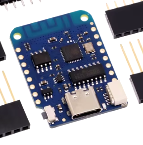
Appearance
Temperature & Humidity Sensors Project
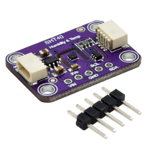
A minimum effort IoT sensor, based on ESP8266 and a SHT40. Connected via cable with SH 1.0 connector. Running Tasmota.
No soldering. No custom software. Assemble, configure and use.
Items needed
Requires the purchase of both board and sensor with the connector as well as the wire.
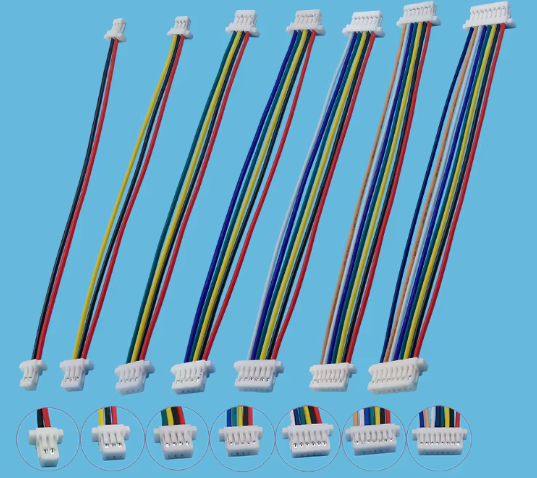
SH 1.0 4 pin wire
Assembly
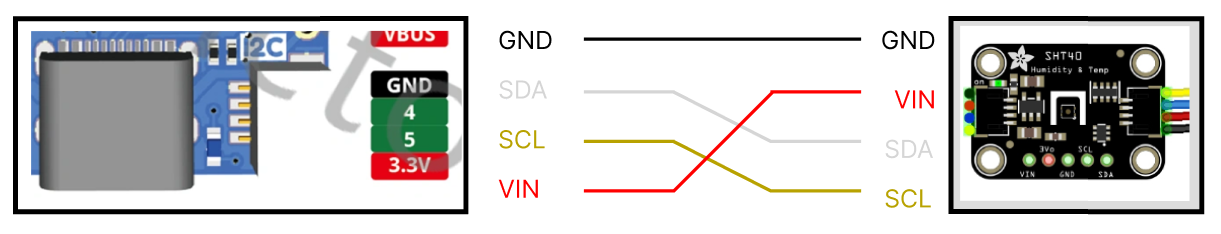
⚠️ Wiring issue
Since the ESP8266 board uses a LOLIN I2C port and the SHT40 is a Adafruit knockoff with QUWIIC port (both based on SH 1.0 connector) the cable wont work out of the box and will need re-splicing or re-making the plug.
Additionally, the cable often has the wrong color order on top of that.
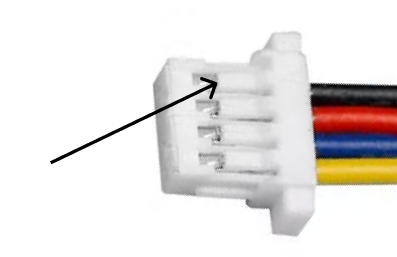
It seems the simplest way is to remove the cables from the plugs and re-insert them in desired order.
You can do it by lifting the white plastic tab while pulling on the cable.
Best to do one at a time with a needle, small pointy knife or scissors.
Software Install
We will use Tasmota to run the sensor.
Installation is done over usb port.
Nowdays you can install it onto the board via online installer.
⚠️ Cable warning
Make sure you have a good cable that is supporting data transfer and not just power
OPTIONAL - Downloading Tasmota Binaries
If the installer has issues installing from source or you wish to install diffrently, you can download the binary tasmota-sensors.bin from:
Link: Tasmota ESP8266 Binaries
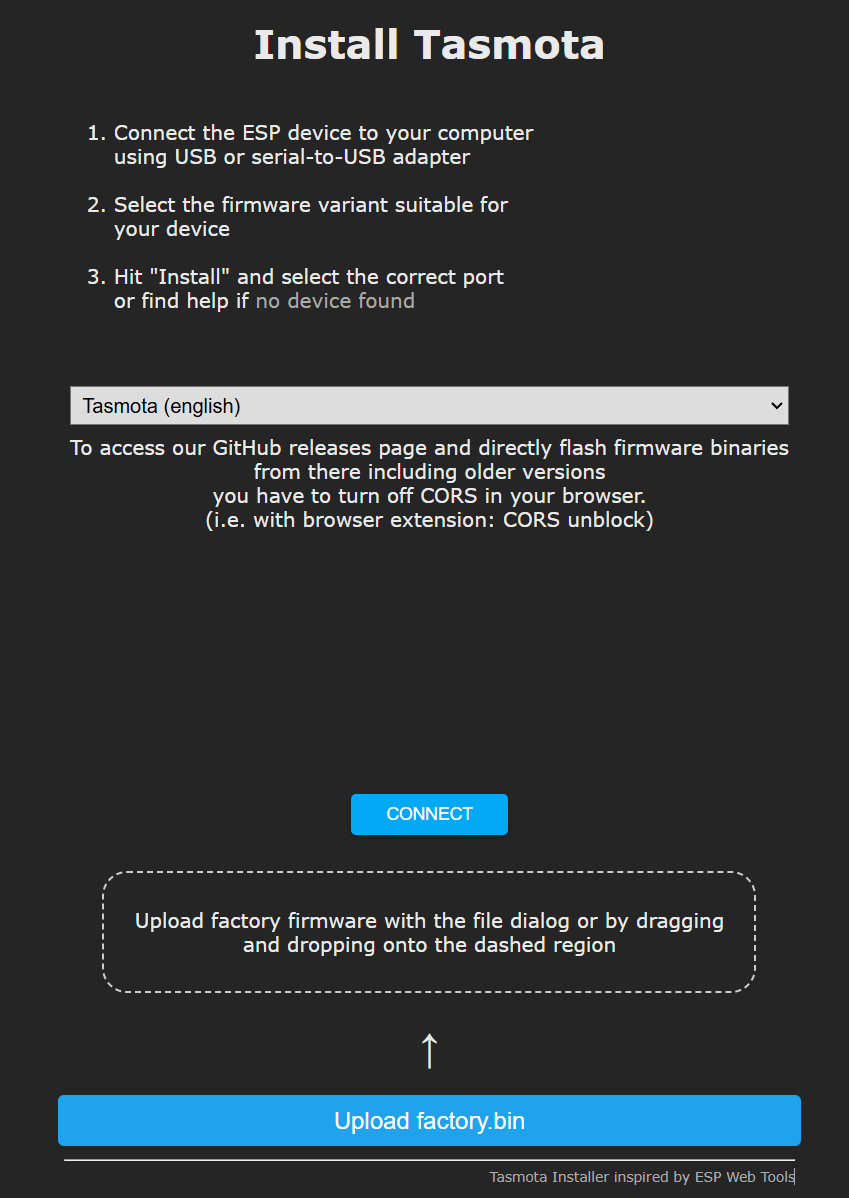
- Go to online installer:
Link: Online Tasmota Installer
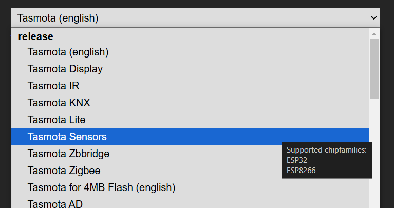
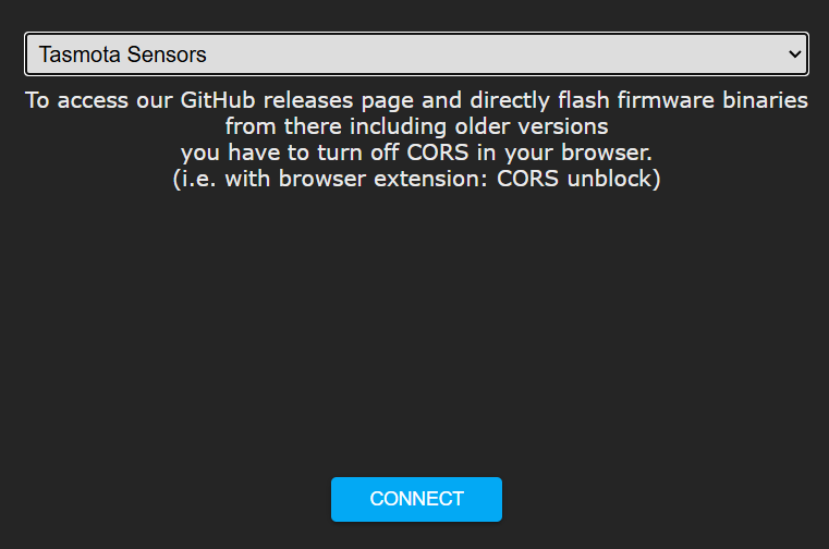
- Select “Tasmota Sensors” from the dropdown
- Plug in the board into the computer
ℹ️ You should hear the new device detected sound. If not, the cable could be an issue
Click “Connect”
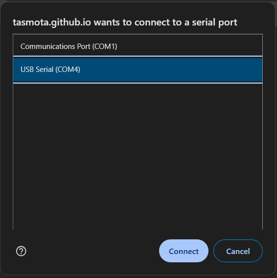
- Select the COM port the board is connected to
ℹ️ If unsure which COM port that is, unplug the board, take note of ports and plug back in to see which is a new one
⚠️ If this popup is not appearing, there might be permissions issues with the browser.
⚠️ If the device is not showing up, your computer might require esp drivers
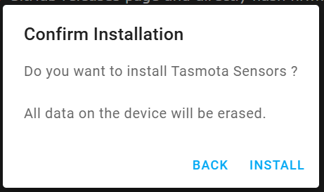
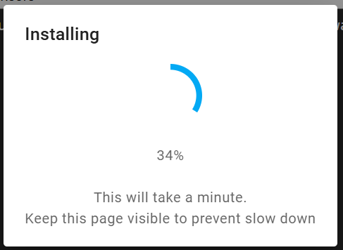
- Go through the installation process and Wifi configuration
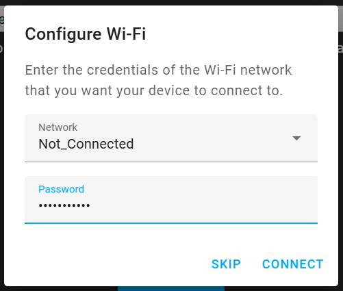
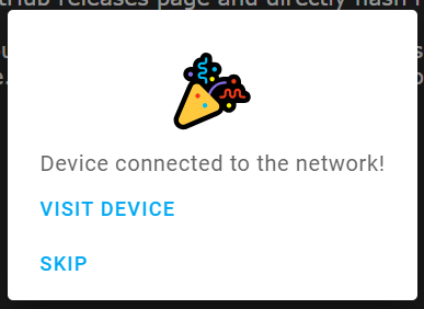
Finally, press “Visit Device” to open the web ui and proceed too…..
Software Configuration
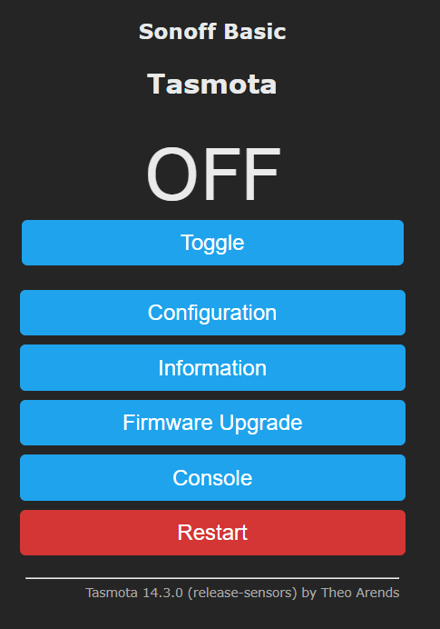
This is the default interface. We will now configure tasmota and the sensor. As we do, the device will restart every time we save the changes
MQTT Broker Config
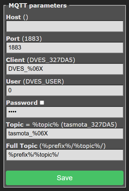
Now, go to Main Menu → Configuration → Configure MQTT
Enter your host and blank for user and password
Change the topic to something more useful. Like “th1” or something.
Press Save. The board will reboot.
OPTIONAL - Broker connection without user/pass
Once we configure the broker connection… does your broker require username and password for connecting? If NOT, then to allow a blank username/password we need to run a command.
⚠️ This needs to be done once you configured the MQTT broker section
Go to Main Menu → Console. Into the console, paste:
backlog mqttuser 0; mqttpassword 0; restart 1
and hit enter. The board will reboot.
Source: How to connect Tasmota to MQTT Broker with no Password
Sensor Config
Now, lets configure the SHT40 sensor. We will use the official guide for SHT30
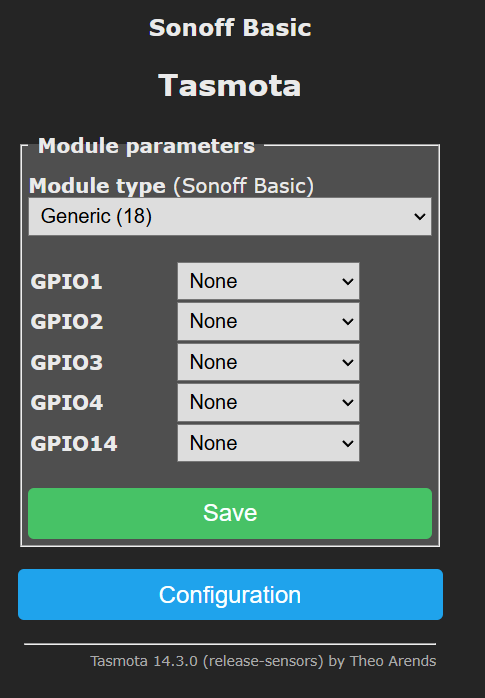
Go to Main Menu → Configuration → Configure Module
Change Module type to Generic (18)
Press Save. The board will reboot.
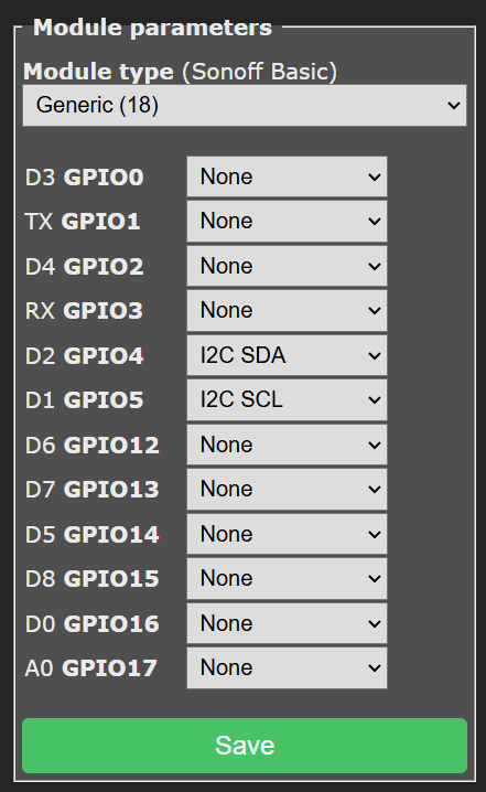
Go to Main Menu → Configuration → Configure Module again. This time pin list will be longer.
Set D2 GPIO4 to I2C SDA
Set D1 GPIO5 to I2C SCL
Press Save. The board will reboot.
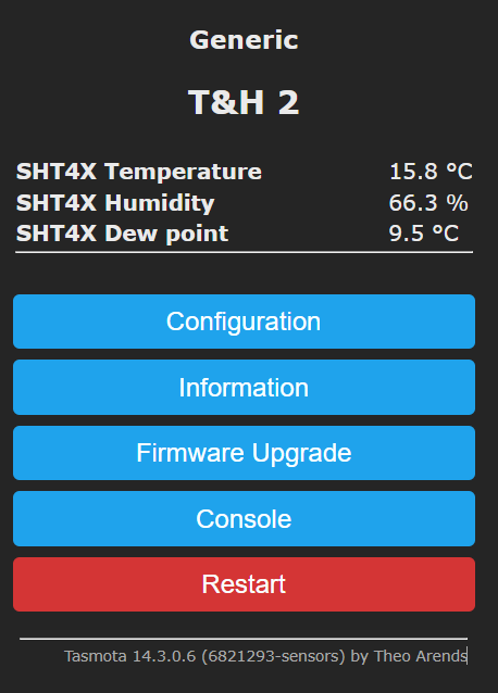
At this point the main screen should contain your sensor info and look something like this
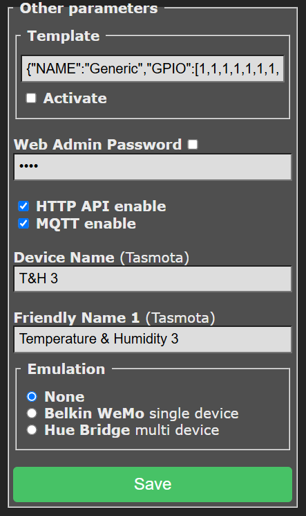
Go to Main Menu → Configuration → Configure Other
Change the Device Name and Friendly Name to something useful
Press Save. The board will reboot.
OPTIONAL - Sensor Polling Period
If you would like to change the default sensor polling period from default 300 seconds (5 min):
Go to Main Menu → Console and enter command
TelePeriod 600
to increase the polling period to 600 seconds (10 minutes)
For the info on the command go to https://tasmota.github.io/docs/Commands/#mqtt and search for TelePeriod
OPTIONAL - Sensor offset calibration
HumOffset and TempOffset are also notable and useful commands that let you callibrate/offset the sensors. See documetation for details.
Basic MQTT usage
To grab the sensor data, subscribe to topic tele/th2/SENSOR where “th2” is the topic we configured in the MQTT Config. For additional mqtt topics and commands, refer to the official documentation for Tasmota
Docs: Tasmota Documentation
While testing, you might want to get the board to emit the sensor data, rather then waiting the set inverval. Re-running TelePeriod command in Main Menu → Console will get the board to emit the last known data.
Quick FAQ
Q: Why ESP8266 not ESP32?
A: Could not find ESP32 with a I2C port. They are also more expensive, and there is absolutely no need for the extra power. ESP8266 is just fine for the job.
Q: Why SHT40?
A: Because after reading around, they seem to be a pretty good sensor. And I was able to find it with the I2C port.